Building graphical interface elements by using the System.Drawing namespace
In this tutorial we will learn about Graphics Object, The Windows Forms Coordinate System, Drawing Text on a Form, Drawing Shapes and Working with images.
Understanding The Graphics Object
Graphics handling in Visual Basic .NET is based on GDI+ (Graphics Device Interface). A graphics device interface allows you to display graphics on a screen or a printer without having to handle the details of a specific display device. All that you need to do is to make calls to methods supported by the GDI+ classes and those methods make the corresponding calls to individual device drivers as needed to handle the screen or printer.
To create a graphics object
Receive a reference to a graphics object as part of the System.Windows.Forms.PaintEventArgs in the System.Windows.Forms.Control.Paint event of a form or control. This is usually how you obtain a reference to a graphics object when creating painting code for a control.
-or-
Call the System.Windows.Forms.Control.CreateGraphics method of a control or form to obtain a reference to a System.Drawing.Graphics object that represents the drawing surface of that control or form. Use this method if you want to draw on a form or control that already exists.
-or-
Create a System.Drawing.Graphics object from any object that inherits from System.Drawing.Image. This approach is useful when you want to alter an already existing image.
Let quickly see an example:
Click here for the Sample Code
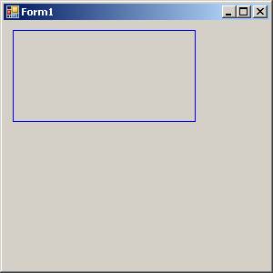
You can manage the state of the Graphic Object easily as can be seen in the following code fragment
Click here for the Sample Code
The above code generates the output as shown below:
Understanding The Windows Forms Coordinate System
GDI+ uses three coordinate spaces: world, page, and device. World coordinates are the coordinates used to model a particular graphic world and are the coordinates you pass to methods in the .NET Framework. Page coordinates refer to the coordinate system used by a drawing surface, such as a form or control. Device coordinates are the coordinates used by the physical device being drawn on, such as a screen or sheet of paper.
When you make the call myGraphics.DrawLine(myPen, 0, 0, 160, 80), the points that you pass to the System.Drawing.Graphics.DrawLine method—(0, 0) and (160, 80)—are in the world coordinate space. Before GDI+ can draw the line on the screen, the coordinates pass through a sequence of transformations. One transformation, called the world transformation, converts world coordinates to page coordinates, and another transformation, called the page transformation, converts page coordinates to device coordinates.
Transforms and Coordinate Systems
Suppose you want to work with a coordinate system that has its origin in the body of the client area rather than the upper-left corner. Say, for example, that you want the origin to be 100 pixels from the left edge of the client area and 50 pixels from the top of the client area. The following illustration shows such a coordinate system.
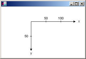
When you make the call myGraphics.DrawLine(myPen, 0, 0, 160, 80), you get the line shown in the following illustration.
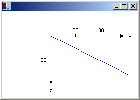
The coordinates of the endpoints of your line in the three coordinate spaces are as follows:
World
(0, 0) to (160, 80)
Page
(100, 50) to (260, 130)
Device
(100, 50) to (260, 130)
The code snippet to draw the line shown in the above picture is given below:
myGraphics.TranslateTransform(100, 50)
myGraphics.DrawLine(myPen, 0, 0, 160, 80)
{mospagebreak}
.
.
Drawing Text on a Form
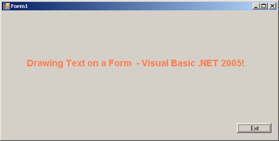
Drawing text on a Form can be achieved by the following method. You can use the System.Drawing.Graphics.Drawsting method of the System.Drawing.Graphics class to draw text. This example will be using the System.Windows.Forms.PaintEventArgs e, which is a parameter of System.Windows.Forms.PaintEventHandler. Let us see a demo for this task. In a new project add the following codes:
Click here for the Sample Code
You have to add a button and set the value for the text property to “Exit”.
The drawText method takes one parameter System.Windows.Forms.PaintEventArgs e. This method is called from the System.Windows.Forms.PaintEventHandler method which causes the Text to be drawn on the Form.
We declare a variable myText and assign it a value also. We also declare a fontFamily as an object of type FontFamily Which sets the name for the font family. We also declare a font object of the type Font and set values for its properties like FontFamily, Size, Style and Graphics Unit. This defines the visual properties of the Font that we want to display. The DrawString method which takes four parameters is used to draw Text. Here you can choose the type of brush by declaring your won brush. The out put is given below for the above project.
Drawing Shapes
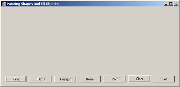
We have seen how to create the Graphic object, draw a line and also to draw shapes. Now we shall see drawing other shapes. Drawing shapes and filling the shape with solid color or with gradient is accomplished by the various methods available in the Graphics Object. Let us walkthrough an example that demonstrates the power, flexibility of the language and also its richness. Create new Windows application in Visual Basic Express and add seven buttons to it. The window should look like the graphic given below:
The System.Drawing.Drawing2D namespace contains rich classes that support and extend the facilities for drawing. You can define you own pen with the following statement:
Dim MyPen As New Pen(MyColor, 5)
The pen that you have created will write in MyColor with thickness 5 pints. You can also define any type of brush from a range of brushes and assign a wide range of values that suit your needs. The methods of Graphics Object also support drawing with methods like, DrawLine, FillEllipse etc.
The GraphicsPath class has methods that help you to draw several shapes and texts at one time and this can be used to enhance the visual richness of the shapes and text. Applications use paths to draw outlines of shapes, fill the interiors of shapes, and create clipping regions. The graphics engine maintains the coordinates of geometric shapes in a path in world coordinate space.
A path may be composed of any number of figures (subpaths). Each figure is either composed of a sequence of connected lines and curves or a geometric shape primitive. The starting point of a figure is the first point in the sequence of connected lines and curves. The ending point is the last point in the sequence. The starting and ending points of a geometric shape primitive are defined by the primitive specification.
All these features have been used in the following demo:
Click here for the Sample Code
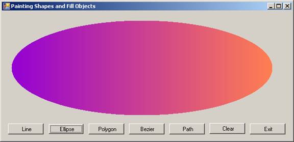
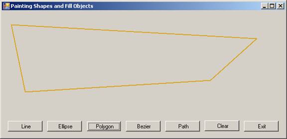
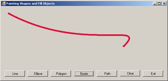
The output of the five options are given below:
Draw Line:

Draw Gradient Filled Ellipse:
Draw Polygon:
Draw Bezier:
Draw Text and Shapes with GraphicPath
{mospagebreak}
.
.
Working with images
Visual Basic .NET comes with lots of features that makes working with images a real pleasure. We shall quickly see why this is so!
We deal with images in GDI+ that fall into three broad categories:
Two-dimensional (2-D) vector graphics
Imaging
Typography
2-D Vector Graphics
Two-dimensional vector graphics are concerned with primitives; such as lines, curves, and figures; that are specified by sets of points on a coordinate system. For example, a straight line is specified by its two endpoints, and a rectangle is specified by a point giving the location of its upper-left corner and a pair of numbers giving its width and height. A simple path is specified by an array of points that are connected by straight lines. A Bezier spline is a sophisticated curve specified by four control points.
Imaging
There are some kinds of pictures that are difficult or impossible to display with the techniques of vector graphics. For example, the pictures on toolbar buttons and the pictures that appear as icons are difficult to specify as collections of lines and curves. High-resolution digital photographs are even more difficult to create with vector techniques. Images of this type are stored as bitmaps, which are arrays of numbers that represent the colors of individual dots on the screen. GDI+ provides the System.Drawing.Bitmap class for displaying, manipulating, and saving bitmaps. GDI+ provides extensive support for this complex task.
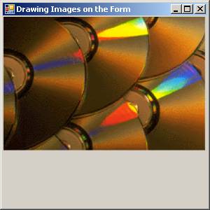
Drawing images on forms and buttons can be achieved using the drawImage() method of the Graphics Object.
To a new project in the Visual Basic Express add the following lines of code to the form.
This output generated by this program is given below
Click here for the Sample Code
Programming in graphics with Visual Basic is a separate area of interest and this is huge. Visual Basic 2005 is loaded with a rich collection of Classes and objects that perform a variety of operations. Programming games applications is both fun and a challenge to the pursuer where you will be solving several challenges. So explore and you will undoubtedly have a rich and enthralling experience.
[catlist id=175].